Hi All, Our website moved to a new URL. Please bookmark the new link: https://ns2bloggers.blogspot.com/

Friday, 11 September 2015

CONGESTION WINDOW "cwnd" IN NS2

In TCP Networks, the most important factor that determines behavior is its congestion window size. In NS2, we can handle it with using cwnd command. In NS, every TCP type classes have a variable named "cwnd" that contains the congestion window size of the TCP Module. In here we can use 'set' command to return a value. 

We can write it as;
set  tcp1  [new  Agent/TCP/Reno]
set  cwnd1  [ $tcp1  set  cwnd_ ]

To obtain TCP's CWND value frquently;

  • We can easily make the NS simulation system repeatedly read the value (say, after every 0.1 sec of simulation time).
  • Schedule a read operation repeatedly

Proc plotWindow {tcpSource outfile} {
     global ns

     set now [$ns now]
     set cwnd [$tcpSource set cwnd_]

  #  Print TIME CWND   for  gnuplot to plot progressing on CWND   
     puts  $outfile  "$now $cwnd"

     $ns at [expr $now+0.1] "plotWindow  $tcpSource  $outfile"
  }

  • The procedure plotWindow takes a paramter tcpSource which is a TCP agent.So you can use the procedure to plot the CWND from any number of TCP flows.


  • The procedure plotWindow takes an output file ID outfile.You should first open an output file (or use "stdout") in the main program.

Examining progressing of CWND in TCP (Reno)

#Make a NS simulator   
  set ns [new Simulator]

  # Define a 'finish' procedure
  proc finish {} {
     exit 0
  }

  # Create the nodes:
  set n0 [$ns node]
  set n1 [$ns node]
  set n2 [$ns node]
  set n3 [$ns node]
  set n4 [$ns node]
  set n5 [$ns node]

  # Create the links:
  $ns duplex-link $n0 $n2   2Mb  10ms DropTail
  $ns duplex-link $n1 $n2   2Mb  10ms DropTail
  $ns duplex-link $n2 $n3 0.3Mb 200ms DropTail
  $ns duplex-link $n3 $n4 0.5Mb  40ms DropTail
  $ns duplex-link $n3 $n5 0.5Mb  30ms DropTail

  # Add a TCP sending module to node n0
  set tcp1 [new Agent/TCP/Reno]
  $ns attach-agent $n0 $tcp1

  # Add a TCP receiving module to node n4
  set sink1 [new Agent/TCPSink]
  $ns attach-agent $n4 $sink1

  # Direct traffic from "tcp1" to "sink1"
  $ns connect $tcp1 $sink1

  # Setup a FTP traffic generator on "tcp1"
  set ftp1 [new Application/FTP]
  $ftp1 attach-agent $tcp1
  $ftp1 set type_ FTP               (no necessary)

  # Schedule start/stop times
  $ns at 0.1   "$ftp1 start"
  $ns at 100.0 "$ftp1 stop"

  # Set simulation end time
  $ns at 125.0 "finish"    (Will invoke "exit 0")   


  ##################################################
  ## Obtain CWND from TCP agent
  ##################################################

  proc plotWindow {tcpSource outfile} {
     global ns

     set now [$ns now]
     set cwnd [$tcpSource set cwnd_]

  ###Print TIME CWND   for  gnuplot to plot progressing on CWND
     puts  $outfile  "$now $cwnd"

     $ns at [expr $now+0.1] "plotWindow $tcpSource  $outfile"
  }

  $ns  at  0.0  "plotWindow $tcp1  stdout"   // Start the probe !!    


  # Run simulation !!!!
  $ns run


his NS Prog prints the (time, cwnd) to the terminal: click here
This NS Prog prints the (time, cwnd) to the output file "WinFile": click here

To plot the window progressing from "winfile", do:

UNIX>> gnuplot
gnuplot>> plot "WinFile" using 1:2 title "Flow 1" with lines 1

Note:
In case you wonder why the cwnd plot look so different, It's because the setting of some parameters.
Add the following statements to the simulation to get the one I used in class:

  # ########################################################
  # Set Queue Size of link (n2-n3) to 10 (default is 50 ?)
  # ########################################################
  $ns queue-limit $n2 $n3 10


  # ########################################################
  # TCP parameters:
  # ########################################################    
  $tcp1 set window_ 8000
  $tcp1 set packetSize_ 552

This NS Prog will draw the CWND: click here

Postscript: Analyzing multiple TCP flows

The easiest way to analyze the behavior of multiple TCP is to open one file to store the progression of one TCP agent's variable values.

 TCP Agents

  set tcp1 [new Agent/TCP/Reno]
  ...
  set tcp2 [new Agent/TCP/Reno]
  ...


  set outfile1  [open  "WinFile1"  w]
  set outfile2  [open  "WinFile2"  w]


  $ns  at  0.0  "plotWindow $tcp1  $outfile1"

  $ns  at  0.0  "plotWindow $tcp2  $outfile2"     

Plot data of  TCP 1 will be store in file "WinFile1"

Plot data of  TCP 2 will be store in file "WinFile2"

Friday, 4 September 2015

NETWORK EMULATOR: AN OVERVIEW

Emulators are characters with the emulation ability.Emulation means the ability to introduce the simulator into a live situation/network. Special objects within the simulator are capable of introducing live traffic into the simulator and injecting traffic from the simulator into the live network. There are two primary types of uses for such a facility, depending on whether the simulator appears to end stations as a router or as another end station. In the first case, live traffic can pass through the simulator (transparently to endpoints) and be affected by objects within the simulation, or by other traffic on the live network. In the second case, the simulator can include traffic sources or sinks that communicate with real-world entities. The first type of use is currently more developed than the second type.
The emulation facility can be subdivided into two modes:
  • opaque mode -- live data treated as opaque data packets
  • protocol mode -- live data may be interpreted/generated by simulator

In opaque mode, the simulator treats network data as uninterpreted packets. In particular, real-world protocol fields are not directly manipulated by the simulator. In opaque mode, live data packets may be dropped, delayed, re-ordered, or duplicated, but because no protocol processing is performed, protocol-specific traffic manipulation scenarios (e.g. ``drop the TCP segment containing a re transmission of sequence number 23045'') may not be performed. In protocol mode, the simulator is able to interpret and/or generate live network traffic containing arbitrary field assignments.
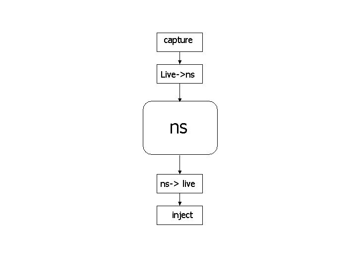
The interface between the simulator and live network is provided by a collection of objects including tap agents and network objects. Tap agents embed live network data into simulated packets and vice-versa. Network objects are installed in tap agents and provide an entry point for the sending and receipt of live data. Figure 1 illustrates how these objects are used for emulation. Both objects are described in the following sections.
 Interaction of emulator objects with the simulator

When using the emulation mode, a special version of the system scheduler is used: the RealTime scheduler. This scheduler uses the same underlying structure as the standard calendar-queue based scheduler, but ties the execution of events to real-time.
  • OPAQUE MODEL
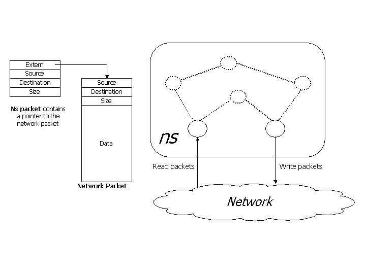
 Packets are passed through the simulator without being interpreted
The simulator acts like a router allowing real-world traffic to be passed through without being manipulated. The ns packet contain a pointer to the network packet. Network packets may be dropped, delayed, re-ordered or duplicated by the simulator. Opaque mode is useful in evaluating the behavior of real-world implementations when subjected to adverse network conditions that are not protocol specific.
  • PROTOCOL MODEL
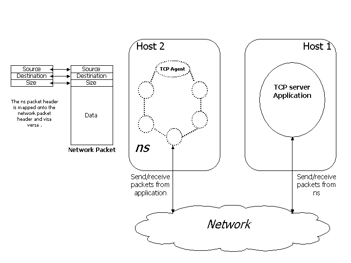
Packets are generated by a TCP agent that interacts transparently with a real-world TCP server.


The simulator is used as an end-point to generate TCP traffic. A TCP agent within ns interacts with a real-world TCP server and can receive data from the external application. nse allow supports ICMP, ARP and TCP NAT agents. The protocol mode can be used for end to end application testing, protocol and conformance testing.

Real-Time Scheduler
The real-time scheduler implements a soft real-time scheduler which ties event execution within the simulator to real time. Provided sufficient CPU horsepower is available to keep up with arriving packets, the simulator virtual time should closely track real-time. If the simulator becomes too slow to keep up with elapsing real time, a warning is continually produced if the skew exceeds a pre-specified constant ``slop factor'' (currently 10ms).

Tap Agents
The class TapAgent is a simple class derived from the base Agent class. As such, it is able to generate simulator packets containing arbitrarily-assigned values within the ns common header. The tap agent handles the setting of the common header packet size field and the type field. It uses the packet type PT_LIVE for packets injected into the simulator. Each tap agent can have at most one associated network object, although more than one tap agent may be instantiated on a single simulator node.

Network Objects
Network objects provide access to a live network (or to a trace file of captured network packets). There are several forms of network objects, depending on the protocol layer specified for access to the underlying network, in addition to the facilities provided by the host operating system. Use of some network objects requires special access privileges where noted. Generally, network objects provide an entrypoint into the live network at a particular protocol layer (e.g. link, raw IP, UDP, etc) and with a particular access mode (read-only, write-only, or read-write). Some network objects provide specialized facilities such as filtering or promiscuous access (i.e. the pcap/bpf network object) or group membership (i.e. UDP/IP multicast). The C++ class Network is provided as a base class from which specific network objects are derived. Three network objects are currently supported: pcap/bpf, raw IP, and UDP/IP. Each are described below.

Pcap/BPF Network Objects
These objects provide an extended interface to the LBNL packet capture library (libpcap). The pcap library is available from LBNL here. This library provides the ability to capture link-layer frames in a promiscuous fashion from network interface drivers (i.e. a copy is made for those programs making use of libpcap). It also provides the ability to read and write packet trace files in the ``tcpdump'' format. The extended interface provided by ns also allows for writing frames out to the network interface driver, provided the driver itself allows this action. Use of the library to capture or create live traffic may be protected; one generally requires at least read access to the system's packet filter facility which may need to be arranged through a system administrator.
The packet capture library works on several UNIX-based platforms. It is optimized for use with the Berkeley Packet Filter (BPF) and provides a filter compiler for the BPF pseudomachine machine code. On most systems supporting it, a kernel-resident BPF implementation processes the filter code, and applies the resulting pattern matching instructions to received frames. Those frames matching the patterns are received through the BPF machinery; those not matching the pattern are otherwise unaffected. BPF also supports sending link-layer frames. This is generally not suggested, as an entire properly-formatted frame must be created prior to handing it off to BPF. This may be problematic with respect to assigning proper link-layer headers for next-hop destinations. It is generally preferable to use the raw IP network object for sending IP packets, as the system's routing function will be used to determine proper link-layer encapsulating headers.

Pcap/File Network Objects
These objects are similar to the Pcap/BPF objects, except that network data is taken from a trace file rather than the live network. As such, the notion of promiscuous mode and the naming of a particular interface (available to the BPF objects) are not available for the file objects. In addition, the ability to create trace files is still under development. This facility will provide the ability to create tcpdump-compatible trace files.

IP Network Objects
These objects provide raw access to the IP protocol, and allow the complete specification of IP packets (including header). The implementation makes use of a raw socket. In most UNIX systems, access to such sockets requires super-user privileges. In addition, the interface to raw sockets is somewhat less standard than other types of sockets. The class Network/IP provides raw IP functionality plus a base class from which other network objects implementing higher-layer protocols are derived.

UDP/IP Network Objects
These objects provide access to the system's UDP implementation along with support for IP multicast group membership operations.

Courtesy: NS2 Official

Thursday, 30 July 2015

WI-MAX MODULE FOR NS 2.28 SIMULATOR

Introduction
The Network Simulator 2 (NS-2) is a popular discrete event simulator target at networking research. This tool can suport simulation of TCP, routing, and MAC protocols over wired and wireless networks. Although it's possible to simulate wireless local area network (IEEE 802.11), ad hoc networks and satellites networks, ns does not provide a WiMAX module. This project implements a WiMAX module based on the IEEE 802.16 standard for the ns-2 simulator, release 2.28. The focus of this implementation is the MAC layer and its mechanisms for bandwidth allocation and QoS support. The module implements the 802.16 five service flow types and their bandwidth request/grant mechanisms; moreover, it allows users to configure the QoS requirements of applications. Service flows are modeled by finite sate machines that capture how each service type react to different events. This module supports TDD mode and PMP topology. The wireless channel available in the ns-2 simulator is used. The module design was based on a module (http://portal.acm.org/citation.cfm?id=1273047) designed to simulate the DOCSIS standard. Although code reuse was possible, several modifications in the DOCSIS module code were necessary to make it compliant to the IEEE 802.16 standard.

Installation

To install the patch, follow the instructions below:

  • Download the software ns-allinone-2.28 package
  • Download the latest ns-2 WiMAX module source code.
  •  Unzip the ns-2 WiMAX module source code file.
  • Put the files from "mac" directory into ns-allinone-2.28\ns-2.28\mac.
  • Put the files which are in common and tcl respectively into ns-allinone-2.28\ns-2.28\common and ns-allinone-2.28\ns-2.28\tcl.
  • Modify the Makefile.in as follows;After the sentence mac/mac-802_3.o add:
  1. mac/mac-802_16-base.o mac/mac-802_16-ss.o mac/mac-802_16-bs.o \
  2. mac/mac-802_16-FSM.o mac/mac-802_16-timers.o \

  • Go to the ns-allinone-2.28/ns-2.28 directory and execute "./configure", "make clean" and "make".

Download


Documentation
The paper "Simulator for WiMAX networks", accepted for publication in Simulation Modelling Practice and Theory, presents a detailed description for the WiMAX module.
Description of the WiMAX module available from the IEEE Xplore Digital Library and presented at PIMRC 2007, Athens, Greece.
Document of the WiMAX module implementation - Download pdf or View html
Description of the uplink scheduler implemented in the WiMAX module available from the IEEE Xplore Digital Library and presented at GLOBECOM 2007, Washington DC, USA.

For More, Click Here

Friday, 24 July 2015

DRIVER LESS CARS...........TESTING STARTED......!!!!

Imagine a town with crosswalks but no pedestrians, cars and trucks but no drivers. Welcome to Mcity, a fake "town" built by researchers who are testing out the driverless cars of the future.
The controlled test environment, which opened today (July 20) at the University of Michigan (U-M) in Ann Arbor, covers 32 acres (the size of about 24 football fields) and contains all the trappings of a real suburb or small city. There is an entire network of roads lined with sidewalks, streetlights, stop signs and traffic signals. There's even a "downtown" area complete with fake building facades and outdoor dining areas.The idea behind Mcity is simple: test out new driverless car innovations in a human-free environment before these technologies are unleashed in the real world."Mcity is a safe, controlled, and realistic environment where we are going to figure out how the incredible potential of connected and automated vehicles can be realized quickly, efficiently and safely," Peter Sweatman, director of the Mobility Transformation Center (MTC) at U-M, said in a statement.
The roads of Mcity are built to stand up to "rigorous, repeatable" testing, according to MTC officials. While Mcity drivers don't have to contend with real pedestrians, there will be one mechanical foot-traveler (a robotlike machine named Sebastian) that steps out into traffic to see whether the automated cars can hit the brakes in time. The simulated city also features a traffic circle, a bridge, a tunnel, some unpaved roads, and even a four-lane highway with entrance and exit ramps, according to a report by Bloomberg Business.
In addition to evaluating fully automated, or driverless, cars, the researchers also hope to test out so-called connected vehicles within Mcity's limits. Connected cars can either communicate with one another (vehicle-to-vehicle control, or V2V) or with pieces of equipment, such as traffic lights, that are located near roadways (vehicle-to-infrastructure control, or V2I).
Even the smallest details of Mcity have been planned out in advance to replicate conditions that connected and automated vehicles could face in the real world. For example, there are street signs covered up with graffiti, and faded yellow and white lane markings line the streets.
Mcity is just one part of a much larger project that MTC and its partner organizations are establishing in an effort to get a whole fleet of connected and driverless cars on the road in Ann Arbor by 2021. In addition to the fake city, MTC is also continuing to launch connected and semi-autonomous cars on real roadways. Eventually, the University of Michigan and the Michigan Department of Transportation said they hope to put 20,000 connected cars on the roads of southern Michigan.

Courtesy: livescience

Thursday, 23 April 2015

CONTROLLED DELAY ACTIVE QUEUE MANAGEMENT IN NS2

Hi Guys,
 Controlled Queue Delay is a modern AQM mechanism for solving buffer bloat[Persistently Full Buffer Problem]. The solution for persistently full buffers, AQM (active queue management), has been known for two decades but has not been widely deployed because of implementation difficulties and general misunderstanding about Internet packet loss and queue dynamics. Unmanaged buffers are more critical today since buffer sizes are larger, delay-sensitive applications are more prevalent, and large (streaming) downloads common. The continued existence of extreme delays at the Internet’s edge can impact its usefulness and hamper the growth of new applications.

This article aims to provide part of the bufferbloat solution, proposing an innovative approach to AQM suitable for today’s Internet called CoDel (for Controlled Delay, pronounced like “coddle”). This is a “no-knobs” AQM that adapts to changing link rates and is suitable for deployment and experimentation in Linux-based routers (as well as silicon).

In this post, we providing patch codes for CoDel along with ns2 versions.

To download patch, Click here
To download ns2, Click here

>> First untar ns2 and change directory to ns-allinone-2.35
>> Copy patch file into the folder and type following command in terminal
patch -pl < CoDel-ns-2.31.patch 
>> Then, Configure, Make & Install

For more, Click here

Friday, 6 February 2015

TOUR DE NS2: REVEALING PROGRAMMING STYLE

Friends,
Today we are going to have a look in why we run ns2 program as "ns program.tcl"?
Before that we have to go through basic C++ programmings in ns2.Consider a basic C++ instruction only program i .e for example; we are considering a program to calculate time taken for a packet travel from uppermost node to lower most node with the time taken to travel packet between each nodes (t) are constant (say t=1ms) and the number of nodes as n. (say n=10). And we have to find out overall time taken to reach packet to lowermost node. The C++ program new.cc is given below and after compiling we get a executable file "new".
//new.cc
main(){
float time = 0 , t = 1;
int i, n = 10;
 for(i = 1; i < n; i++)
time = time+i ;
printf("Overall time is  %f seconds.\n",time);
}
Now we execute the program from terminal, we can see the following results;
>> ./new
Overall time is 10.0 seconds.
But this programming style is not perfect. If the time to reach packet from one node to another is different and the number of nodes are changed then every time we have to change C++ program. To avoid this we can use input arguments. If we have more that one or two inputs we can provide it from terminal by using input arguments. For that normally we use argc and argv commands. The variable argc shows the number of input arguments and the variable argv contains all the inputs needed for programmer. The following C++ program shows it.
//new.cc
int main(int argc, char* argv[]) {
float time = 0, t = atof(argv[0]);
int i, n = atoi(argv[1]);
for(i = 1; i < n; i++)
time = time + i ;
printf("Overall time is %f seconds\n",time);
}
Now we execute the program from terminal, we can see the following results;
>> ./new 1 10
Overall time  is 10.0 seconds.
>> ./new 3 8
Overall time  is 24.0 seconds.
This programming scheme also have flexibility problem and which is inconvenient as input increases. So we went for most convenient form of  programming using configuration file. In this scheme the input data is used to pick input arguments. Consider a C++ program new.cc with configuration file con.txt and Function readArgFromFile(fp,a) reads the configuration file associated with a file pointer “fp,” and sets variables.
//new.cc
int main(int argc, char* argv[]) {
float time = 0, t[9];
FILE* fp = fopen(argv[1],"w");
int i, n = readArgFromFile(fp,a);
for(i = 1; i < n; i++)
time = time + i ;
printf("Overall time is %f seconds\n",time);
fclose(fp);
}
//con.txt
Number of node = 10
Time = 1 4 3 5 2 7 9 5 3
Now we execute the program from terminal, we can see the following results;
>> ./new con.txt
Overall time  is 30.0 seconds.
By modifying that con.txt file, we get various results.

Now we are looking towards the ns2 and i hope you all get some clue about what i am talking too. In ns2, we know that program is run by using command "ns programname.tcl". The TCL file programname.tcl is used as the input argument providing configuration file and  “ns” is a C++ executable file that generate after compiling using make and install function. The input configuration file specifies system parameters and all other configurations related to it.

I hope you all get it. 
Stay tuned for more updates........!!!!!!!!!

Thursday, 5 February 2015

TOUR DE NS2: REVEALING SECRETS BEHIND COMMAND "MAKE" AND "MAKEFILE"

Friends,
We are decided to introduce a new segment in our blog named as "ToUr De Ns2" to get you more familiar with ns2 directories, folders and commands that we used in the ns2. We hope it gives you all a deep knowledge in ns2. We need all your supports and prayers. Comments and new ideas are welcomed.

Now we are going to have a deep look in command make. We all know that ns2 is a research tool. So all of the researchers are tried to customize files or to add new C++ modules in ns2 directory. During this time, it is necessary to recompile all the files that related or depend with it. So we need an effective command for recompilation of all files because manual recompilation is not possible. For that we here use a UNIX utility tool called as "make". This command has a significant role in development process. It keeps track of all the files created throughout the development process. By keeping track, it recompile the inter dependencies exist among these files; which may have been modified. The command syntax that we write in terminal to call is;
 make [-f filename]
Here make command recompiles the source code according to the descriptor file "filename" and the descriptor file is optional. So the command inside bracket is optional. By default the descriptor file is "Makefile". So if we not provided the filename, command automatically consider Makefile as descriptor file.

DESCRIPTOR FILE: MAKEFILE:

This file contains the name of source codes that have to execute, their inter dependency and how the file is to recompile. These things are specified using a specific dependency rule or by using a particular arrangement code names called as dependency rule. It contain three components; target,depfile&command
The syntax is given as;
<target1> [<target2> ...] : <depfile1> [<depfile2> ...]
<command1> [<command2> ...]
Here, the target file is the file which is needed to be compile and depfile are the files which are dependency file which is specified after semicolon(:) and also file inside bracket are optional ones. And the line below that shows the command that to regenerate the target file.
Example: 
# makefile of channel
OBJS = main.o
COM = cc
channel : ${OBJS}
${COM} -o channel ${OBJS}
main.o : main.c
${COM} -c main.c
clean :
rm ${OBJS}
Here, the target file is channel and that depends the file main.o and which is showed in third line and on the forth line the command showed to execute the recompiling. And the process repeats in the following lines. Final two line shows the clean function which is used to clean the dependency object file that are not neede after the recompilation. The UNIX command “cc -c file.c” compiles the file “file.c” and creates an object file “file.o,” while the command “cc -o file.o” links the object file “file.o” and create an executable file “file.”.

NS2 MAKEFILE:

Makefile in the ns2 is located in the ns2.xx directory and while we open it we can see the details of files needed to recompile. And in that file, we can mainly see the following keywords;

  • INCLUDES = : The files or items that seen inside this category is to be seen in ns2 environment.
  • OBJ_CC = & OBJ_STL = : It constitute the entire ns2 object files.
  • NS_TCL_LIB = : We have to add the Tcl files of  ns2.
If a new C++ module is developed, then its corresponding object file name with “.o” extension should be added in OBJ_CC and OBJ_STL and Tcl file name should be added NS_TCL_LIB.

If you created a new C++ module with corresponding files .cc,.h and .tcl (say new.cc,new.h and new.tcl) and also created a new folder new inside the ns2 directory. After this we have to to the following;
1. Include a string “-I./new” into the Line beginning with INCLUDES = in the “Makefile.”
2. Include a string “new/new.o” into the Line beginning with OBJ_CC = or OBJ_STL = in the “Makefile.”
3. Include a string “new/new.tcl” into the Line beginning with NS_TCL_LIB = in the “Makefile.”
4. Run “make” from the terminal.
After running “make,” an executable file “ns” is created and this file “ns” to run simulation.

Continue with a new topic in following posts......!!!!
Thank You.
Have a Nice day.