Hi All, Our website moved to a new URL. Please bookmark the new link: https://ns2bloggers.blogspot.com/

Friday 11 September 2015

CONGESTION WINDOW "cwnd" IN NS2

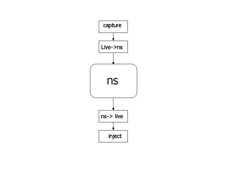
In TCP Networks, the most important factor that determines behavior is its congestion window size. In NS2, we can handle it with using cwnd command. In NS, every TCP type classes have a variable named "cwnd" that contains the congestion window size of the TCP Module. In here we can use 'set' command to return a value. 

We can write it as;
set  tcp1  [new  Agent/TCP/Reno]
set  cwnd1  [ $tcp1  set  cwnd_ ]

To obtain TCP's CWND value frquently;

  • We can easily make the NS simulation system repeatedly read the value (say, after every 0.1 sec of simulation time).
  • Schedule a read operation repeatedly

Proc plotWindow {tcpSource outfile} {
     global ns

     set now [$ns now]
     set cwnd [$tcpSource set cwnd_]

  #  Print TIME CWND   for  gnuplot to plot progressing on CWND   
     puts  $outfile  "$now $cwnd"

     $ns at [expr $now+0.1] "plotWindow  $tcpSource  $outfile"
  }

  • The procedure plotWindow takes a paramter tcpSource which is a TCP agent.So you can use the procedure to plot the CWND from any number of TCP flows.


  • The procedure plotWindow takes an output file ID outfile.You should first open an output file (or use "stdout") in the main program.

Examining progressing of CWND in TCP (Reno)

#Make a NS simulator   
  set ns [new Simulator]

  # Define a 'finish' procedure
  proc finish {} {
     exit 0
  }

  # Create the nodes:
  set n0 [$ns node]
  set n1 [$ns node]
  set n2 [$ns node]
  set n3 [$ns node]
  set n4 [$ns node]
  set n5 [$ns node]

  # Create the links:
  $ns duplex-link $n0 $n2   2Mb  10ms DropTail
  $ns duplex-link $n1 $n2   2Mb  10ms DropTail
  $ns duplex-link $n2 $n3 0.3Mb 200ms DropTail
  $ns duplex-link $n3 $n4 0.5Mb  40ms DropTail
  $ns duplex-link $n3 $n5 0.5Mb  30ms DropTail

  # Add a TCP sending module to node n0
  set tcp1 [new Agent/TCP/Reno]
  $ns attach-agent $n0 $tcp1

  # Add a TCP receiving module to node n4
  set sink1 [new Agent/TCPSink]
  $ns attach-agent $n4 $sink1

  # Direct traffic from "tcp1" to "sink1"
  $ns connect $tcp1 $sink1

  # Setup a FTP traffic generator on "tcp1"
  set ftp1 [new Application/FTP]
  $ftp1 attach-agent $tcp1
  $ftp1 set type_ FTP               (no necessary)

  # Schedule start/stop times
  $ns at 0.1   "$ftp1 start"
  $ns at 100.0 "$ftp1 stop"

  # Set simulation end time
  $ns at 125.0 "finish"    (Will invoke "exit 0")   


  ##################################################
  ## Obtain CWND from TCP agent
  ##################################################

  proc plotWindow {tcpSource outfile} {
     global ns

     set now [$ns now]
     set cwnd [$tcpSource set cwnd_]

  ###Print TIME CWND   for  gnuplot to plot progressing on CWND
     puts  $outfile  "$now $cwnd"

     $ns at [expr $now+0.1] "plotWindow $tcpSource  $outfile"
  }

  $ns  at  0.0  "plotWindow $tcp1  stdout"   // Start the probe !!    


  # Run simulation !!!!
  $ns run


his NS Prog prints the (time, cwnd) to the terminal: click here
This NS Prog prints the (time, cwnd) to the output file "WinFile": click here

To plot the window progressing from "winfile", do:

UNIX>> gnuplot
gnuplot>> plot "WinFile" using 1:2 title "Flow 1" with lines 1

Note:
In case you wonder why the cwnd plot look so different, It's because the setting of some parameters.
Add the following statements to the simulation to get the one I used in class:

  # ########################################################
  # Set Queue Size of link (n2-n3) to 10 (default is 50 ?)
  # ########################################################
  $ns queue-limit $n2 $n3 10


  # ########################################################
  # TCP parameters:
  # ########################################################    
  $tcp1 set window_ 8000
  $tcp1 set packetSize_ 552

This NS Prog will draw the CWND: click here

Postscript: Analyzing multiple TCP flows

The easiest way to analyze the behavior of multiple TCP is to open one file to store the progression of one TCP agent's variable values.

 TCP Agents

  set tcp1 [new Agent/TCP/Reno]
  ...
  set tcp2 [new Agent/TCP/Reno]
  ...


  set outfile1  [open  "WinFile1"  w]
  set outfile2  [open  "WinFile2"  w]


  $ns  at  0.0  "plotWindow $tcp1  $outfile1"

  $ns  at  0.0  "plotWindow $tcp2  $outfile2"     

Plot data of  TCP 1 will be store in file "WinFile1"

Plot data of  TCP 2 will be store in file "WinFile2"

Friday 4 September 2015

NETWORK EMULATOR: AN OVERVIEW

Emulators are characters with the emulation ability.Emulation means the ability to introduce the simulator into a live situation/network. Special objects within the simulator are capable of introducing live traffic into the simulator and injecting traffic from the simulator into the live network. There are two primary types of uses for such a facility, depending on whether the simulator appears to end stations as a router or as another end station. In the first case, live traffic can pass through the simulator (transparently to endpoints) and be affected by objects within the simulation, or by other traffic on the live network. In the second case, the simulator can include traffic sources or sinks that communicate with real-world entities. The first type of use is currently more developed than the second type.
The emulation facility can be subdivided into two modes:
  • opaque mode -- live data treated as opaque data packets
  • protocol mode -- live data may be interpreted/generated by simulator

In opaque mode, the simulator treats network data as uninterpreted packets. In particular, real-world protocol fields are not directly manipulated by the simulator. In opaque mode, live data packets may be dropped, delayed, re-ordered, or duplicated, but because no protocol processing is performed, protocol-specific traffic manipulation scenarios (e.g. ``drop the TCP segment containing a re transmission of sequence number 23045'') may not be performed. In protocol mode, the simulator is able to interpret and/or generate live network traffic containing arbitrary field assignments.
The interface between the simulator and live network is provided by a collection of objects including tap agents and network objects. Tap agents embed live network data into simulated packets and vice-versa. Network objects are installed in tap agents and provide an entry point for the sending and receipt of live data. Figure 1 illustrates how these objects are used for emulation. Both objects are described in the following sections.
 Interaction of emulator objects with the simulator

When using the emulation mode, a special version of the system scheduler is used: the RealTime scheduler. This scheduler uses the same underlying structure as the standard calendar-queue based scheduler, but ties the execution of events to real-time.
  • OPAQUE MODEL
 Packets are passed through the simulator without being interpreted
The simulator acts like a router allowing real-world traffic to be passed through without being manipulated. The ns packet contain a pointer to the network packet. Network packets may be dropped, delayed, re-ordered or duplicated by the simulator. Opaque mode is useful in evaluating the behavior of real-world implementations when subjected to adverse network conditions that are not protocol specific.
  • PROTOCOL MODEL
Packets are generated by a TCP agent that interacts transparently with a real-world TCP server.


The simulator is used as an end-point to generate TCP traffic. A TCP agent within ns interacts with a real-world TCP server and can receive data from the external application. nse allow supports ICMP, ARP and TCP NAT agents. The protocol mode can be used for end to end application testing, protocol and conformance testing.

Real-Time Scheduler
The real-time scheduler implements a soft real-time scheduler which ties event execution within the simulator to real time. Provided sufficient CPU horsepower is available to keep up with arriving packets, the simulator virtual time should closely track real-time. If the simulator becomes too slow to keep up with elapsing real time, a warning is continually produced if the skew exceeds a pre-specified constant ``slop factor'' (currently 10ms).

Tap Agents
The class TapAgent is a simple class derived from the base Agent class. As such, it is able to generate simulator packets containing arbitrarily-assigned values within the ns common header. The tap agent handles the setting of the common header packet size field and the type field. It uses the packet type PT_LIVE for packets injected into the simulator. Each tap agent can have at most one associated network object, although more than one tap agent may be instantiated on a single simulator node.

Network Objects
Network objects provide access to a live network (or to a trace file of captured network packets). There are several forms of network objects, depending on the protocol layer specified for access to the underlying network, in addition to the facilities provided by the host operating system. Use of some network objects requires special access privileges where noted. Generally, network objects provide an entrypoint into the live network at a particular protocol layer (e.g. link, raw IP, UDP, etc) and with a particular access mode (read-only, write-only, or read-write). Some network objects provide specialized facilities such as filtering or promiscuous access (i.e. the pcap/bpf network object) or group membership (i.e. UDP/IP multicast). The C++ class Network is provided as a base class from which specific network objects are derived. Three network objects are currently supported: pcap/bpf, raw IP, and UDP/IP. Each are described below.

Pcap/BPF Network Objects
These objects provide an extended interface to the LBNL packet capture library (libpcap). The pcap library is available from LBNL here. This library provides the ability to capture link-layer frames in a promiscuous fashion from network interface drivers (i.e. a copy is made for those programs making use of libpcap). It also provides the ability to read and write packet trace files in the ``tcpdump'' format. The extended interface provided by ns also allows for writing frames out to the network interface driver, provided the driver itself allows this action. Use of the library to capture or create live traffic may be protected; one generally requires at least read access to the system's packet filter facility which may need to be arranged through a system administrator.
The packet capture library works on several UNIX-based platforms. It is optimized for use with the Berkeley Packet Filter (BPF) and provides a filter compiler for the BPF pseudomachine machine code. On most systems supporting it, a kernel-resident BPF implementation processes the filter code, and applies the resulting pattern matching instructions to received frames. Those frames matching the patterns are received through the BPF machinery; those not matching the pattern are otherwise unaffected. BPF also supports sending link-layer frames. This is generally not suggested, as an entire properly-formatted frame must be created prior to handing it off to BPF. This may be problematic with respect to assigning proper link-layer headers for next-hop destinations. It is generally preferable to use the raw IP network object for sending IP packets, as the system's routing function will be used to determine proper link-layer encapsulating headers.

Pcap/File Network Objects
These objects are similar to the Pcap/BPF objects, except that network data is taken from a trace file rather than the live network. As such, the notion of promiscuous mode and the naming of a particular interface (available to the BPF objects) are not available for the file objects. In addition, the ability to create trace files is still under development. This facility will provide the ability to create tcpdump-compatible trace files.

IP Network Objects
These objects provide raw access to the IP protocol, and allow the complete specification of IP packets (including header). The implementation makes use of a raw socket. In most UNIX systems, access to such sockets requires super-user privileges. In addition, the interface to raw sockets is somewhat less standard than other types of sockets. The class Network/IP provides raw IP functionality plus a base class from which other network objects implementing higher-layer protocols are derived.

UDP/IP Network Objects
These objects provide access to the system's UDP implementation along with support for IP multicast group membership operations.

Courtesy: NS2 Official